Making an UART cable for the Nexus 5
Translations: Português (pt-BR)Recently, me and a friend started digging into making the Nexus 5 run the mainline Linux kernel. The purpose of this is, apart from a great learning experience, to make the Nexus 5 run a Linux distro, like PostmarketOS, instead of Android, while also having lifetime updates delivered from the mainline.
Of course, the first thing before getting to coding is to get the UART from the phone to the computer, so that I could read the log messages from early boot of the kernel and figure out the cause of any issue. In the case of the Nexus 5, the UART is on the audio jack, so a way to connect it to the USB of my computer was needed.
I found instructions about the construction of this cable on both the postmarketOS wiki and on the nexus-5-upstream website, which is a project from Brian Masney, who already contributed a lot of patches to upstreaming the Nexus 5.
The information on these pages were conflicting, so I figured it would be best to prototype the circuit first and make sure it worked before soldering it.
Prototyping
I had to prototype using only the components I already had, since I would already buy some components for the final board, and didn't want to do two purchases.
I started following the schematic on the postmarketOS wiki, since it was based on a schematic from Google.
For the audio jack I used an old earphone I had around, and cut it so that I ended up with only the cable with the wires exposed and the connector. I followed the same resistor values on the schematic, using a 1kΩ and two 100Ω resistors in series to get the 1.2kΩ for the voltage divider on the TX pin.
To bridge UART to USB I used the Adafruit FT232H breakout I had. Since it didn't have a 3.3V output, I tried some combination of resistors to divide the 5V. That got me to 3.26V but it still didn't work.
I was almost giving up, but remembered that Brian Masney wrote in that page that it really needs to be at 3.3V, and I also remembered I had an SPI to USB converter board that had a 3.3V regulated output. I decided to try it out.
And after only a minor hiccup, with having to change the baud rate to 115200, what do you know, it worked! 🥳
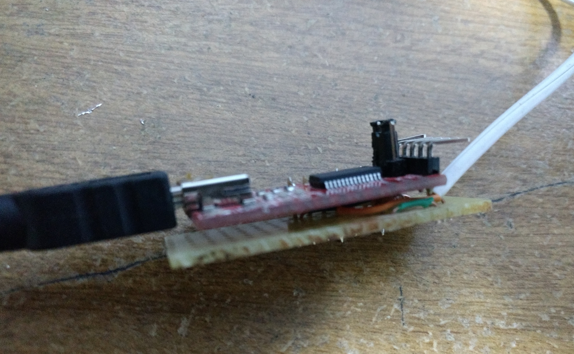
This is how the prototype looked:
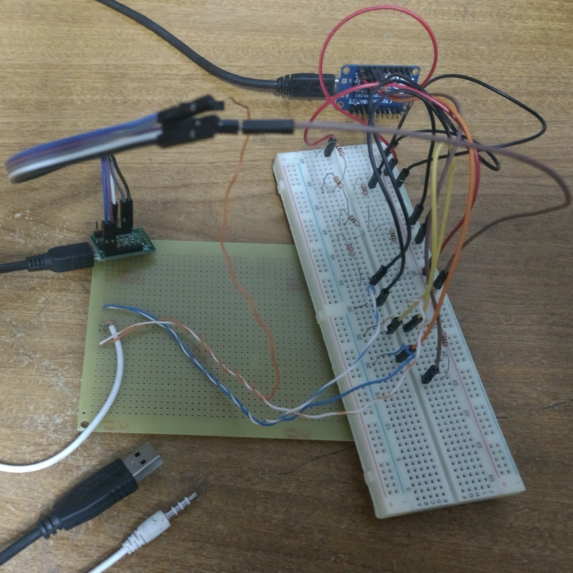
I know, it looks horrible, but hey, it works!
Having got it to work I ordered some more parts to make the circuit neater.
Final board
The components I used to build the board were:
- wires
- 1 universal PCB (at least 9x7 holes)
- 1 1kΩ resistor
- 1 1.2kΩ resistor
- 1 1x7 male pin header
- 1 TRRS audio jack cable (from an old earphone) Note: it really needs to be a TRRS, that is, to have 4 separate conductors.
- 1 UART <-> USB converter (from a store in Brazil, but any with 3.3V is fine)
#/media/File:3.5mm.jpg)
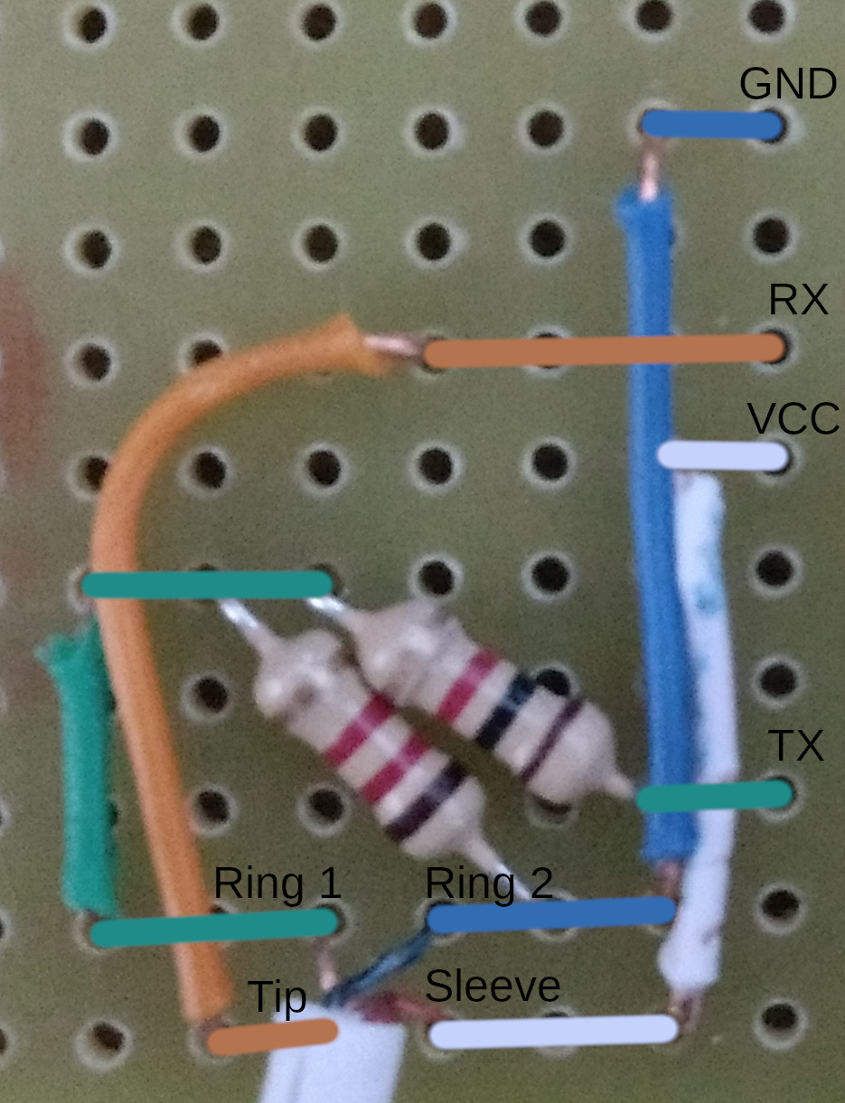
For reference, this is how the pins should be connected (but you really should refer to the schematic at postmarketOS):
| UART pin | Between | Audio jack pin |
|---|---|---|
| RX | — | Tip (TX) |
| TX (at 3.3V) | Voltage divider (1kΩ and 1.2kΩ) | Ring 1 (RX at 1.8V) |
| GND | — | Ring 2 |
| 3.3V | — | Sleeve |
I invested a little time thinking how was the most neat way I could solder the connections and resistors to the board, and I ended up with this:
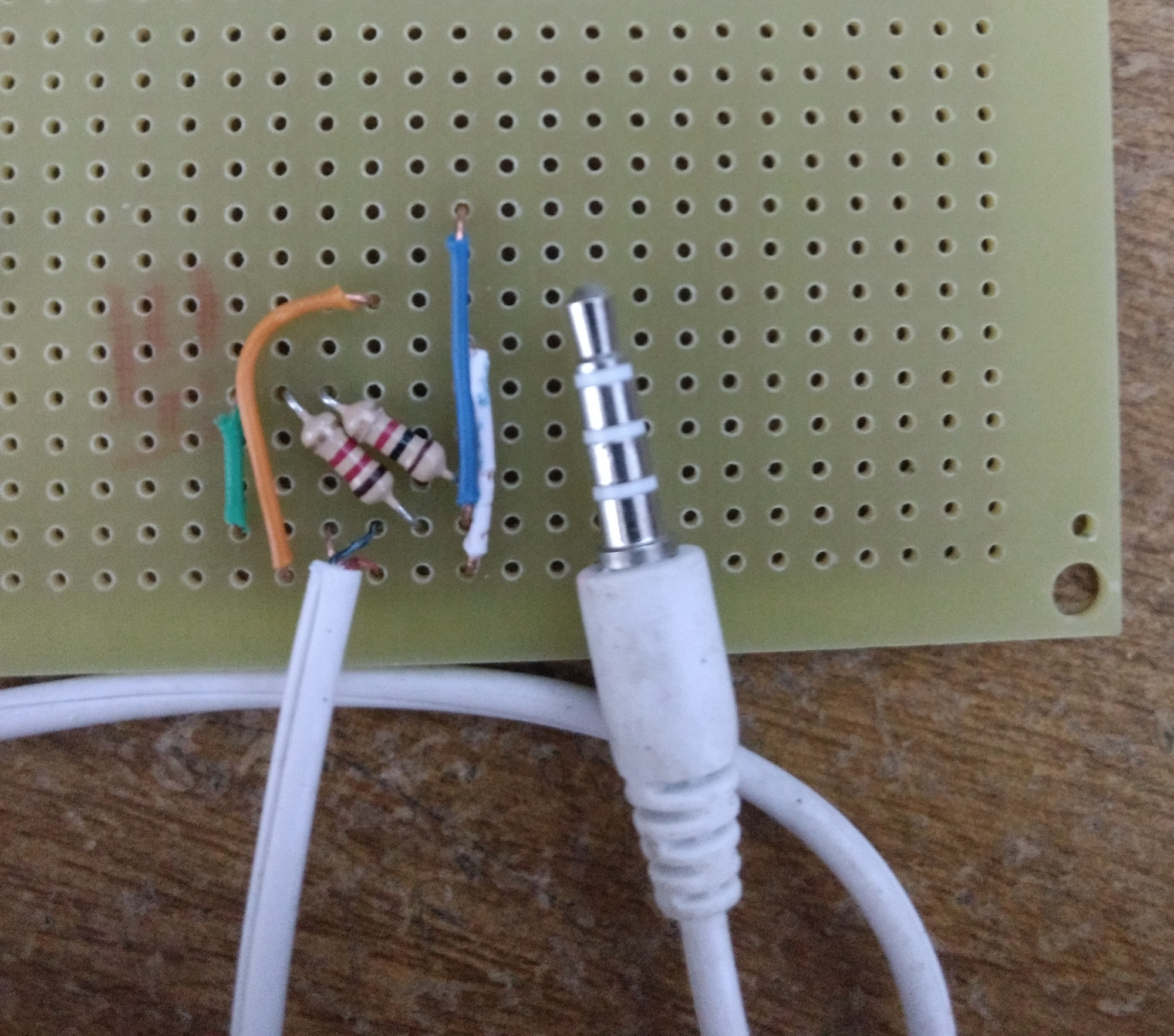
And with the connections on the back side and corresponding pins shown:
My PCB was bigger than the converter board so I sawed it to have approximately the same size (17x7), but the connections only take up a 9x7.
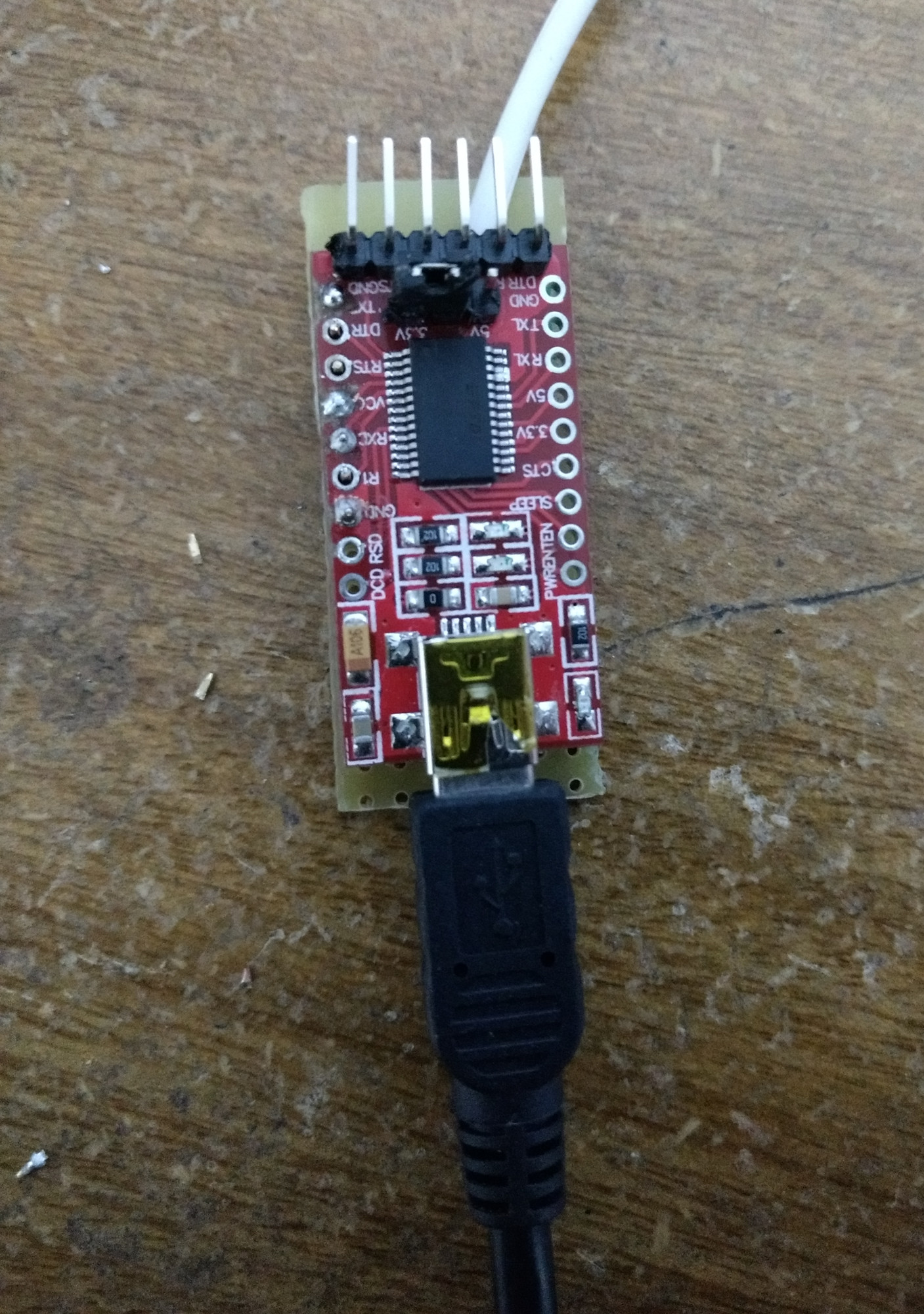
I also changed the jumper position on the UART to USB converter board so that VCC was 3.3V.
Finally I soldered the male pin headers to the converter board, and that on top of my PCB, ending up with a pretty cool 2-story board 😎.
This is how the final board looks:
Testing
After connecting the board's USB to my computer and the audio jack to the Nexus
5, I opened a serial console using picocom with a 115200 baud rate:
picocom /dev/ttyUSB0 -b 115200
And booted the Nexus 5 into fastboot mode by holding the power and volume down buttons, to be greeted with this heartwarming message:
welcome to hammerhead bootloader
[10] Power on reason 80
[10] DDR: hynix
[110] Loaded IMGDATA at 0x11000000
[110] Display Init: Start
[190] MDP GDSC already enabled
[190] bpp 24
[230] Config MIPI_CMD_PANEL.
[230] display panel: ORISE
[230] display panel: Default setting
[360] Turn on MIPI_CMD_PANEL.
[410] Display Init: Done
[410] cable type from shared memory: 8
[410] vibe
[610] USB init ept @ 0xf96b000
[630] secured device: 1
[630] fastboot_init()
[680] splash: fastboot_op
 FASTBOOT MODE
 PRODUCT_NAME - hammerhead
 VARIANT - hammerhead D821(H) 16GB
 HW VERSION - rev_11
 BOOTLOADER VERSION - HHZ20h
 BASEBAND VERSION - M8974A-2.0.50.2.30
 CARRIER INFO - None
 SERIAL NUMBER - ***
 SIGNING - production
 SECURE BOOT - enabled
 LOCK STATE - unlocked
[790] splash: start
[1820] Fastboot mode started
[1820] udc_start()
Since I verified that the pinout on nexus-5-upstream was wrong, I sent a pull request fixing it, so there's no such confusion anymore 😉.
Great! Now that I can read all boot logs I'm ready to dive into the kernel code. Although I'm sure this was the easiest part of the project 😅...