Ledsticker: My first holistic SW + HW project
Translations: Português (pt-BR)It was in the middle of 2019. I was taking classes in Embedded Systems Laboratory and had to make the final project of my choice. I had the idea to do some sort of a Guitar Hero using a keyboard for the input, an 8x8 LED matrix to display the notes and speakers to play the note sounds. The problem was that the university didn't offer the LED matrix or the speakers, so I decided to buy them, with the excuse that I would want to use them later for my personal projects as well.
That project went well, and the end result can be seen on YouTube. Having completed it, I started thinking about what to do with the LED matrix. Eventually, I had an idea I thought was so cool that it just had to be done.
I enjoyed adding cool stickers to my notebook's lid, and had a lot of them, but when you get down to it, stickers aren't that interesting. So what if I used the LED matrix as a sticker? I could glue it to the notebook lid and connect it to the USB port, so it could get power as well as be controlled. I would be able to program anything I wanted to be shown on the matrix.
Prototyping
The first step in turning this into reality was to build a prototype. I already had the LED matrix module, but it received data from an SPI bus, rather than the USB that I wanted to use. I started searching the internet for a circuit that converted USB to SPI and found the MCP2210 IC. I bought some those, but also bought its development board version, with the IC on a board ready to use, to make the initial prototyping easier.
I then searched for software that implemented the interface with MCP2210 and found MCP2210-Library. I started writing my own software to initialize the IC responsible for controlling the LED matrix, MAX7219, (present in the LED matrix module) by calling the library functions to send the SPI data through USB (which MCP2210 then forwarded through the SPI bus to MAX7219).
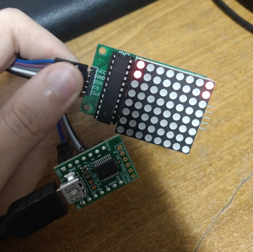
At this point I had the minimum necessary to verify whether the project was viable: the necessary hardware components in their own separate ready-to-use modules, and a minimum software capable of interacting with the ICs and drawing a fixed pattern on the LED matrix. I connected the USB-to-SPI module to the computer and to the LED matrix module and ran my program:
Having confirmed that the project was indeed viable, I started advancing on the necessary steps to make it usable for the end user. The first thing was to make it easy to control the LED matrix for the intended purpose. This is when I decided on the sticker concept, which is central to the project.
Stickers
I wanted it to be possible to show three different things on the LED matrix:
- A static "image", that is, turn a static pattern of LEDs on.
- An animated "image", that is, show a sequence of patterns, each one after some delay.
- An animated "image" but that was dynamically generated from the output of a program, so I could show a simulation of the Game of Life, for example.
To enable the two first use cases, I defined the concept of a static sticker. It is simply a text file containing a sequence of commands that determine what is shown on the matrix. There are commands for turning individual pixels, whole columns or rows, or the whole screen on or off, for updating the screen, etc.
To enable the third use case, I defined the dynamic sticker, which is any program, programmed in any language, that outputs those sticker commands. In this way, a programming language can be used to generate a more complex and dynamic sticker.
So the idea is that the user would execute ledsticker and pass either a
static or dynamic sticker as a parameter. If it was static, the commands would
be read and the LED matrix updated accordingly. Otherwise if it was dynamic, it
would instead be executed and its output used as a static sticker in the same
way.
For all of this to work, I had to both define all sticker commands, as well as
implement a simple parsing for them in my program. As an example of the
commands, the simplest one is on R C, which turns the LED at row R and
column C on.
Finally, to make sure those commands were enough, and also for fun, I implemented some stickers: a single frame with the Creeper face, an animated Tetris, and a dynamically generated simulation of the Game of Life.
Hardware
At this point I had the software fully operational, so I wanted to start tackling the hardware side. I was using separate modules for the LED matrix and the USB-to-SPI, but the objective really was to have it all in a single small PCB, in order to be convenient to attach it to the notebook lid.
But before making the PCB, I had to be sure about the circuit. I had the two separate modules which were known to work, so I used them as a reference and read the datasheets for MAX7219 and MCP2210 in order to create the circuit schematic in KiCad.
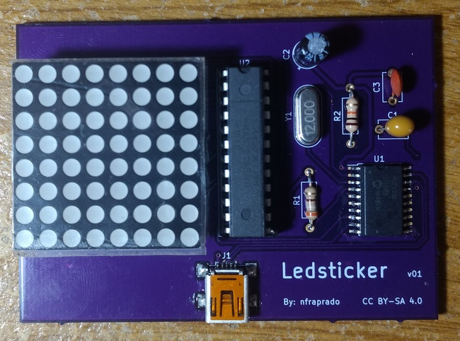
I ended with a schematic containing the two main ICs, MAX7219 and MCP2210, as well as all the other passive components needed to make them work (resistors, capacitors and a crystal), together with the LED matrix and a USB mini connector.
The schematic symbol (and footprint) for the LED matrix (model 1088AS) in particular I had to create myself, since it didn't exist. I followed DigiKey's Intro to KiCad series for that.
With the circuit decided, I soldered all the components and connections in an universal board (would've been easier on a breadboard, but I don't have a good one) to test. The most difficult part of this was that the MCP2210 IC is a Surface Mount Device (SMD), and SMDs aren't meant to be soldered on universal boards. What I did was to order a SMD adapter PCB with the correct pin sizes so I could solder the IC on it and solder it on my board. This is what it all looked like:
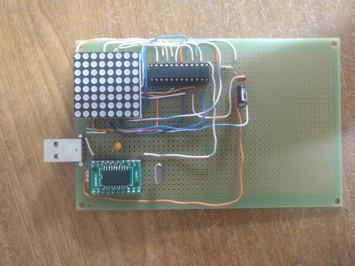
After testing this board with some stickers and concluding that it was working fine, the only final thing to do was the PCB.
PCB
I had never made a PCB before, and the idea of finally learning it was one of the things that motivated me to make this project in the first place.
I learned almost everything from following the DigiKey's Intro to KiCad series I already mentioned. There are a lot of different steps in making a PCB, but they aren't really difficult, just laborious sometimes. Positioning the components in a compact way while also minding the traces that had to be made was very tricky, but it was a fun puzzle.
After finishing the project in KiCad, I ordered the PCB from OSHPark. After 3 long months waiting for it (due to overseas shipping delay due to the pandemic), the board finally arrived.
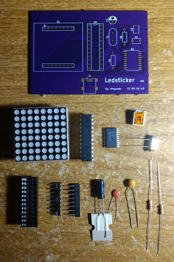
After waiting so long for the board I didn't waste a second to solder. I got all the components and soldered everything on the same day. Here are all the components next to the PCB:
Halfway there (or so I thought):
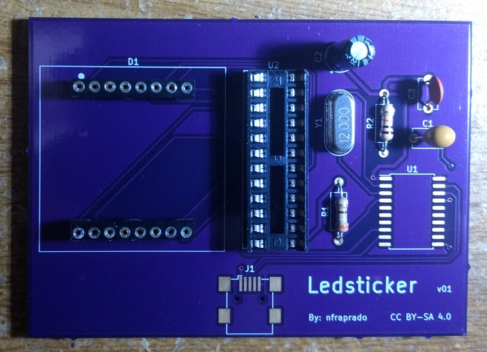
Soldering the SMD components (MCP2210 and USB mini connector) was a lot harder than the rest. The USB mini in particular was nearly impossible. The pads for its 5 pins were almost the same size of the leads themselves, and they weren't very easy to reach with the soldering iron. After multiple tries, I finally got it though. Here is the final board:
Needless to say that it was incredible to see my very own PCB. There's something magical about holding something you designed yourself, that writing software could never provide. Seeing the whole circuit tidily organized in this PCB also felt so much more robust and professional (look at the prototype board again for comparison...).
Results
With everything finally done, the board, and the program, it was time to play. The following gif shows both the command line used to load the sticker and the ledsticker board being updated. Three stickers are loaded one after the other. First a static Creeper face, then a Tetris animation, and finally a Game of Life simulation generated from a python program "in real-time" [1]:
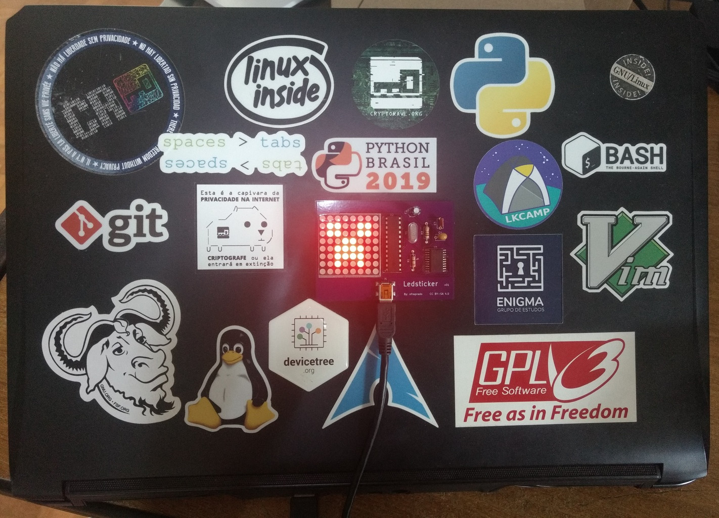
And this marks the project as complete! Wait, but what about gluing the board to the notebook lid? Well, when I started this project, I intended to do that due to a social reason: as I walked with my notebook around the university, people would ask me about it, so I would have an excuse to geek out about it and it would be an interesting conversation starter. With the pandemic, I'm always at home, so doing it would not only be pointless, but then even I wouldn't see it. That's why I'm postponing the attachment to after I'm back going to public spaces again. But just to give an idea of how it would look like, I attached it using tape just for this picture:
Conclusion
This was by far my favorite project I have ever done. It was really a holistic project, where I needed to design both the software and hardware and think about so many different aspects. On the software side I had to create commands to provide a good interface with the user as well as implement the program as a whole (except for the communication with MCP2210). On the hardware side I investigated datasheets to design the circuit, arranged it all to be compact and also created my first PCB!
If you found the project interesting, I invite you to make your own ledsticker board and create your own stickers! Everything is open. You can find the command line program as well as more detailed information on it at ledsticker. The board schematics together with the hardware description can be found at ledsticker-hw. You can also order the PCB directly from OSHPark if you want (I won't receive anything from it). If you do make the board or a sticker, let me know! 😃 (You can find my email in the About page).
| [1] | It isn't really real-time. The dynamic sticker program is run as fast as
it can, filling the input buffer of ledsticker, which is consumed frame
by frame a lot slower, depending on the FPS set. |