CardOS: Now compiling without Arduino!
Translations: Português (pt-BR)In the "CardOS: Writing an OS for the Cardputer" post I shared about the OS that I'm writing for the Cardputer and that the next step was to move away from the Arduino toolchain. It took me two months but I finally did it. The end product was this commit but I'd like to go over the process to get there in this post.
I started by running the Arduino commands to build and flash with verbose output enabled and saving that output for reference. This way I could see what exactly Arduino was doing and understand the steps needed to get from a source to a binary flashed to the chip's memory.
I then got to doing the obvious needed changes to convert from Arduino to C: I
renamed the single source of the project from cardOS.ino to cardOS.c,
changed the setup and loop functions into a main function, and
changed the compilation step in my Makefile to rather than calling Arduino, call
the ESP32 C cross-compiler (xtensa-esp32s3-elf-gcc), which had been
installed on my machine by Arduino and whose path I learned from Arduino's
output.
Next I ran the compilation, and fixed each of the errors that were thrown by the
compiler. Namely I had to add a few includes, function prototypes, change the
way a couple variables were defined and pass the -fno-builtin flag to the
compiler so it would allow me to define my own stdlib functions. With that, I
had an ELF file and needed to figure out how to do the flashing.
From looking through Arduino's output, I learned that esptool.py was the
command used to convert the ELF file into a binary, and then called again to
flash the binary into the chip. Besides the application code, there were other
things being flashed: a bootloader and a partition table. In order to keep
things simple, I did a quick test to verify whether I could ignore them for now
(that is, assume they were already flashed before): I tweaked the OS code and
used the Arduino toolchain to build and flash just that and the tweak showed up
on the Cardputer, so the answer was yes.
With that in mind, I updated the Makefile to call esptool.py to convert the
ELF generated by the compiler and then flash it to the board. At this point I
had the whole procedure to get from the source to the flashed binary on the
board figured out (or so I thought), so I ran it with make upload. But it
did not work, the screen on the cardputer just wouldn't turn on.
I realized assuming all the code would just work in the new setup was too
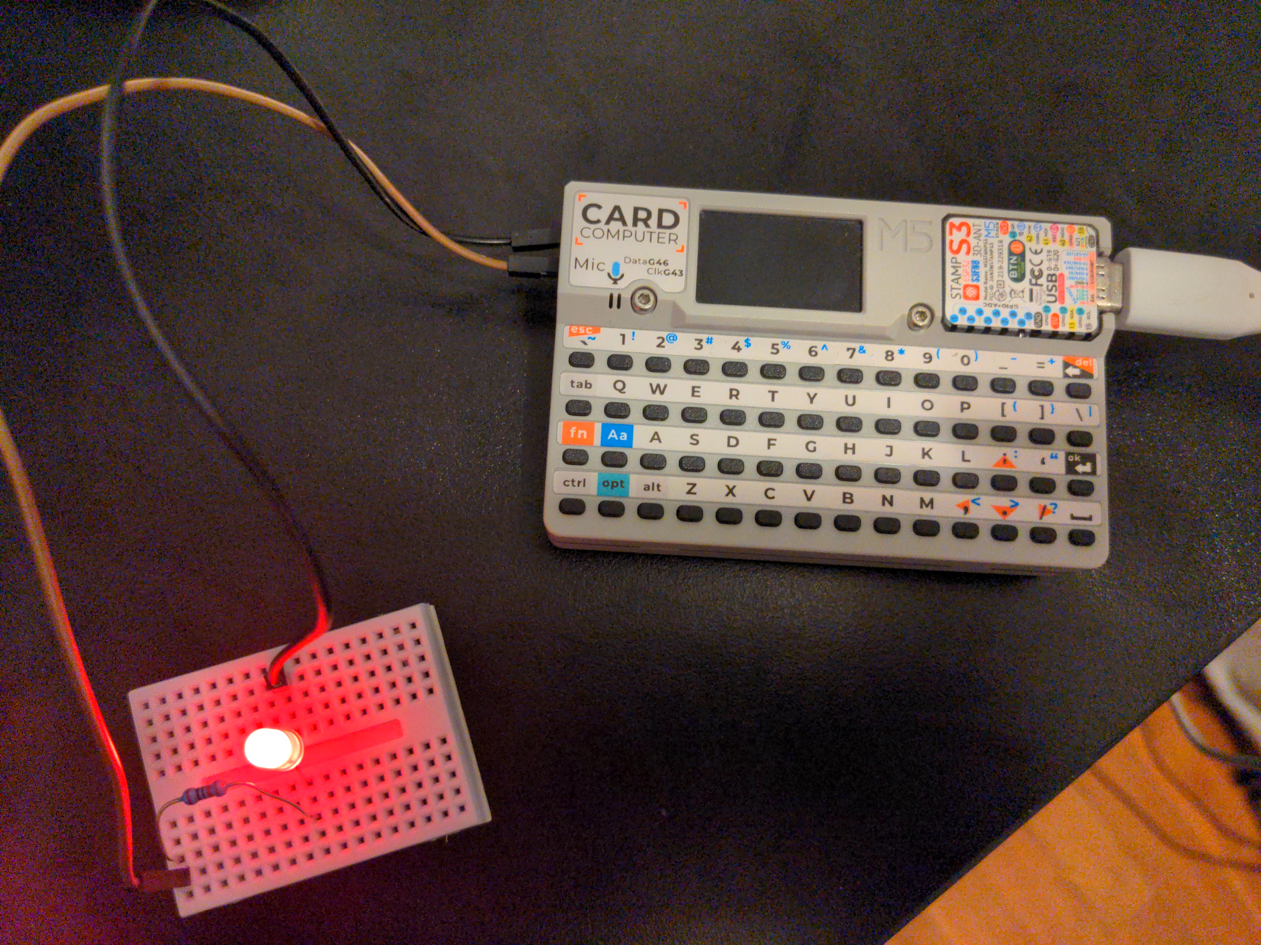
optimistic and decided to simplify the test as much as possible: I changed the
code in main to simply drive the GPIO1 pin high and connected an LED to that
pin. But even then, the LED didn't turn on.
This is where I got stuck for a while. The issue was clearly somewhere in the application binary. My two main theories were that either the binary itself was malformed, or I was missing some initialization code, since Arduino included a bunch of extra files during compilation.
Configuring the addresses in the ELF file
Hoping the issue was in the binary itself, since identifying missing initialization code from Arduino could take a while, I started investigating it.
I used readelf to see the contents of both my ELF and the one generated by
Arduino and compared them. The biggest change in the header was this:
Mine:
Entry point address: 0x40017d
Arduino's:
Entry point address: 0x40376778
Arduino's ELF had much more code in it, so I expected its address to be higher, but this was too much of a difference. It looked like some base address was intentionally set to something different.
I looked up the meaning of the "Entry point address" in an ELF and confirmed that this is the address where execution starts from. So getting it wrong could definitely make my code not work at all.
Looking further through the ELF's content:
Mine:
Program Headers:
  Type           Offset   VirtAddr   PhysAddr   FileSiz MemSiz  Flg Align
  LOAD           0x000000 0x00400000 0x00400000 0x0183c 0x0183c R E 0x1000
  LOAD           0x00183c 0x0040283c 0x0040283c 0x001a1 0x0075c RW  0x1000

 Section to Segment mapping:
  Segment Sections...
   00     .text .rodata .eh_frame
   01     .ctors .dtors .data .bss
Arduino's:
Program Headers:
  Type           Offset   VirtAddr   PhysAddr   FileSiz MemSiz  Flg Align
  LOAD           0x001020 0x3c000020 0x3c000020 0x2a678 0x2a678 RW  0x1000
  LOAD           0x02c000 0x3fc88000 0x3fc88000 0x0c018 0x0d8a8 RW  0x1000
  LOAD           0x039000 0x40374000 0x40374000 0x0ca97 0x0ca98 RWE 0x1000
  LOAD           0x046020 0x42000020 0x42000020 0x1f347 0x1f347 R E 0x1000
  LOAD           0x000000 0x50000000 0x50000000 0x00000 0x00010 RW  0x1000

 Section to Segment mapping:
  Segment Sections...
   00     .flash_rodata_dummy .flash.appdesc .flash.rodata
   01     .dram0.dummy .dram0.data .dram0.bss
   02     .iram0.vectors .iram0.text .iram0.data
   03     .flash.text
   04     .rtc_noinit
After reading up online about ELF program headers and sections this started making sense.
Looking at the program headers on the Arduino ELF, there is indeed an address
very close to the entry point address: 0x40374000 on segment 2. That is the
base address I was suspecting. The code that starts executing then must be in
the iram0.text section, since sections with text in the name represent
code, and that one is mapped to segment 2. The questions that come to mind are:
- Why is this address used?
- How do I set this address in my ELF file?
To answer the first question, I went looking in the ESP32-S3 manual. Figure
4-1 shows a diagram with how each memory range is mapped. The starting address
of the segment used for the entry point code in Arduino, 0x40374000, is
inside the range 0x40370000 - 0x403dffff which is shown as mapped to SRAM
through an instruction bus which totally makes sense!
But reading on, Table 4-1 further breaks down the memory regions and names
the region containing 0x40374000 as "Internal SRAM0". In its description, it
is mentioned the first 16KB of the space can be reserved as a cache for instructions
stored in the flash memory. If we do the math, that means the usable instruction
memory starts at... 0x40374000, exactly the address that was used for the
code segment in Arduino's ELF! So that explains where this address came from.
To sum up, the problem I uncovered is that the ELF file I was generating had the code assigned to addresses that do not map to a memory region that can be accessed by the ESP32's processor to fetch instructions (ie accessible through an instruction bus) and therefore it couldn't be executed.
What was left was to answer the second question: How do I set the right address in my ELF file?
This was a big gap in my knowledge, I had no idea. But looking through Arduino's
output, I saw that the compiler was being passed some .ld files through a
-T parameter. Inside one of them called memory.ld I found addresses
being defined! The -T flag entry in the compiler's manual page revealed these
files were linker scripts, so I knew what I needed to learn about next.
I found this wonderful blog post about linker scripts that taught me
everything I needed to know. With that information I was able to write my linker
script to assign the right addresses to each ELF section: Not only for the code
(.text), but also for the zero-initialized variables (.bss) and other
variables (.data), whose addresses I figured out similarly by referencing
the manual and the Arduino ELF. A few additional sections also had to be
assigned to get rid of linker errors.
As you might have noticed from the ELF contents, Arduino has two code sections,
iram0.text and flash.text, while I only have one, .text. For that
reason, I decided to assign my .text section to flash since it has much more
space. However, there was still no sign of life from the cardputer. Since I
noticed that my code was small enough to fit entirely inside the SRAM, and
Arduino's code started from SRAM, I decided to try that, and it worked!!
The ESP-IDF's application startup flow documentation describes what the second-stage bootloader (which is the one I'm relying on from Arduino) does and does not, and it mentions that it is the application's duty to finish setting up the flash MMU. That is probably why using the flash address for the code didn't work and why Arduino splits the code between an SRAM and a flash part. So at some point I will need to set up access to flash, but for now SRAM was enough.
Initialization code
Now that I had at least an LED turning on, I changed the code back to full operation, that is, initializing the display, rendering the shell and reading the keyboard.
The screen started getting cleared as usual but stopped midway. I removed the screen clearing routine temporarily and the shell prompt was written to the screen. I could type in, but after a short interval my position would go back to the intial one. I realized that the Cardputer was getting reset after a precise interval.
I remembered from the application startup flow documentation that the bootloader enabled the watchdog. And since now the application code was fully provided by me, I had to take care of it myself: either keep feeding the watchdog or disable it.
I chose to disable the watchdog for simplicity (as always), and after referencing the watchdog section in the ESP32-S3 manual and adding a few register writes to the code, it was done: the system no longer crashed. This allowed the shell to stay on screen but it was garbled:
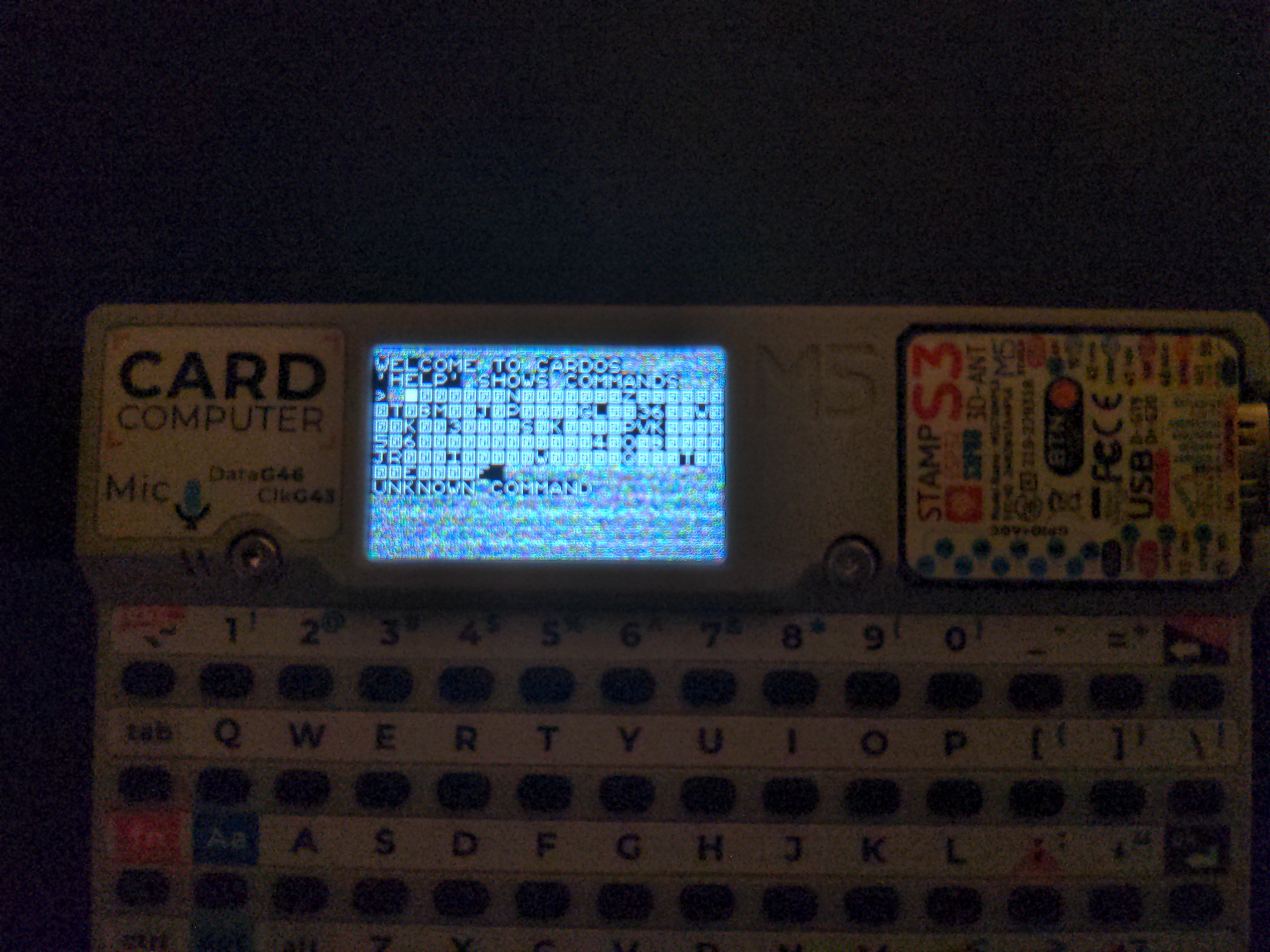
Again, remembering from the application startup flow page, the application
code (me!) was responsible for initializing the .bss section to zero. Since
the .bss section contains the zero-initialized variables, if I don't
initialize it, those variables will contain trash, which is what I was seeing
here.
I didn't know how to do this the proper way, but I could definitely do it the dirty way, that is, manually listing all global variables in a function and zeroing them out 🙈. Which I did and it worked! (Note: I have figured out how to do it properly since and I did it in this commit)
Finally I had a working OS without needing Arduino to build! And that's the full story behind the "Move from Arduino to generic C build flow" commit.
There was still one difference from before the move though, it was much slower. That's because, for the last time referring back to the application startup flow page, the application is supposed to set the CPU clock frequency to the desired value. The default frequency is quite slow, but the startup code implicitly embedded by Arduino would set it to a higher value. I fixed that in a follow up commit.
Further improvements
With the move away from Arduino done, I was finally able to work on some much needed improvements.
The first thing I did was to split the monolithic source file into several different files in this commit. I was really looking forward to this and it felt great to finally do it 😌. Now the code is much more organized, it's easier to find things and to focus on a single component.
I also enabled all the main compiler warnings in this commit, including warning about implicit fallthrough in case switches, which would have saved me some minutes investigating a bug early in this project.
Conclusion
This was another great step for the project. I had a lot of fun and learned so much from it.
The next big thing to tackle is implementing SDcard read and write, and a file system. It will likely be a while before I get that done and come back with an update on the blog. Feel free to check the repository for the latest updates in the meantime if you're curious!